| Mark's site | Webots contest | y | z | w |
| |
Frans van der Klip | ||||
|
|
|||
| • | The Robot Judoka | ||
| • | Leg Model | ||
| • | Judoka Joint Structure | ||
| • | -- | ||
| • | -- | ||
During development of my control program for the "Robot Judo contest" of Cybertronics, I made some items that I like to share (even with competitors). I joined medio Septembert, and submitted my first robot controller program to the match end September 2003. During the course of the contest I will find out more, and put it either here or in the WIKI pages <<add link>> for the Joduka Contest .
Some of the information can be found in on the WIKI
pages for this contest. There all competitors and the contest organisation
can share information.
( If you don't know WIKI, that take a look at it. It is a web site where
many people can contribute to the contents of the web site using an on-line
web page editor. Very nice for a group of people wanting to share information,
like the patricipants of this contest.)
The main source of information is off course the Webots
Contest web site. There you can see the current score board in The Hall
Of Fame, or you can see the life match going on each working day on 14:00 Western
European time (GMT+1 during winter time / daylight savings time).
When you download the special 3D viewer applet, you can even see the match in
3D. You can also download recordings of earlier match rounds and see them in
the 3D viewer.
The contestants must each make a control program for the robot and upload it to the match server of Cybertronics. Every working day a match is held. Two robots control programs are loaded, and they compete against each other for the best of 5 sets, with a maximum set time of 2 minutes.The robot at the first place on the last round (30 April 2004, or 1 May?) wins the prize.
The robot is a walking (you can crawl of course) robot with 2 legs, 2 arms,
a head, a low-resulotion camera, a distance sensor, and a gyro compass. The
control program must be written in Java™, and uses the Webots library
routines to control the robot in the Webots simulator.
The robot model is provided by Cybertronics and cannot be changed: all contenders
have the same "hardware", it is up to their own program how good their
robot performs. Contenders can download the free demo version of Webots (Windows
or Linux), with which they can test their program in their own environment.
(With Java and the free Webots demo, competing does not cost you any extra investment,
but a flat-rate internet connection would be very economic).
A competing robot can be download (the compiled version that is, not the source
code) to hold a test match. And the replay files of each match can be donwloaded
too, so that you can analyse the actual matches with the provided 3D contest
player in your own environment.
The judoka must make the opponent fall. But it is not quite so easy to make a bi-ped robot walk. Several competitors have problems of just staying up by themself.
The contest rules are quite simple and the game looks more like karate, sumo, or boxing then judo. I have not yet seen any robot actually trying to perform a real judo technique.
(sept 2003)
I created a simple model to study the possible movements of the robot leg. In
a side-view picture of the robot leg, the several parts of the leg were "exploded"
at the joints. The drawing contains the separate parts of the leg with the rotation
points of the joints clearly marked. On one of the sides of each joint, a circular
dial is draw, so you can see the angle that two joining parts of the leg make.
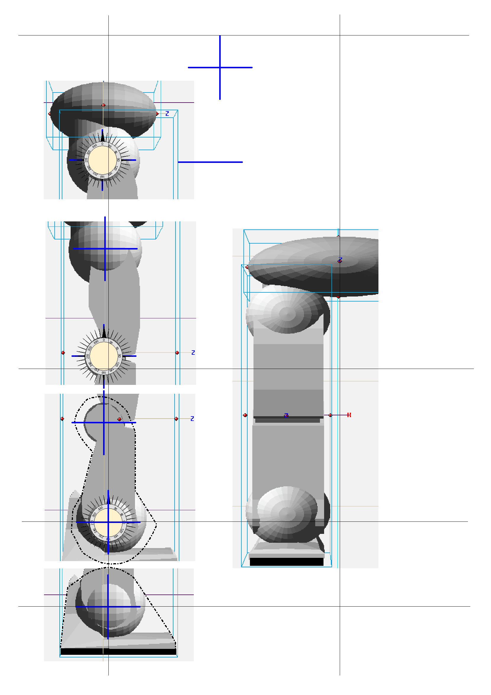
Now you can move your robot leg, and find out what things are possible. Below you can see a foto of my first-made leg.

Of course, this is only a 2D model from the side of a leg. But that movement is very important to walk, and even to remain standing up. (When you fall down, you loose).
(2 October 2003)
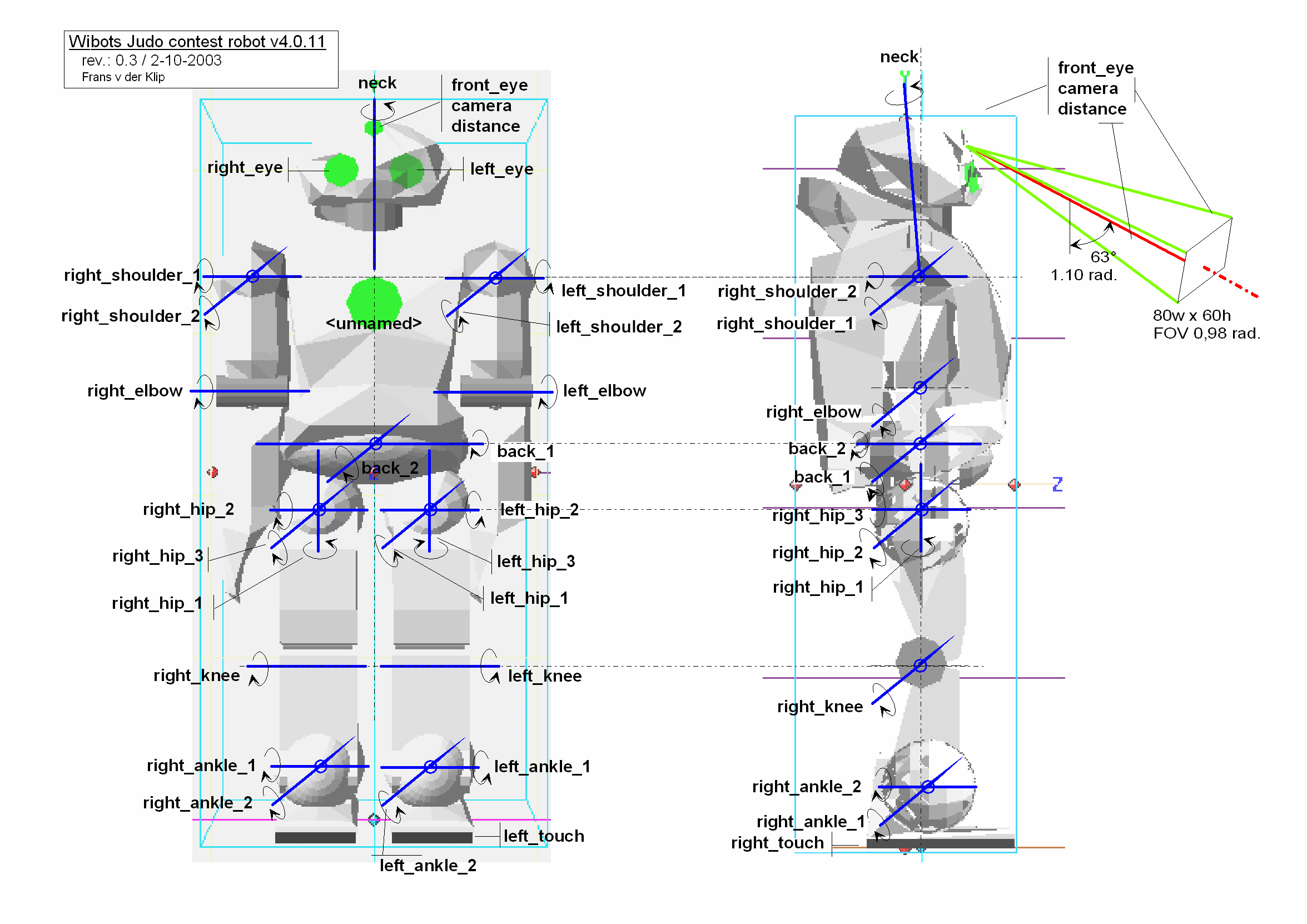
The robot has 21 joints, 5 sensors (a camera and a distance sensor on the head,
2 touch sensors below the feet, and a GPS device (for this contest) returning
only rotation angles). The definition robot model itself is not very easy to
read, as it is in VRML language. Therefore I took 2 screenshots and added markers
(showing the axis of rotation) for each joint and sensors. You see below a small
version of this drawing. A larger copy
suitable for printing (2351x1621, 86 kB, PNG format) is available (click the
image).
In case you need better scaling of leters and lines (not of the background robot image), there is a version in EMF (Enhances Window MetaFile) format, size 956 kB. If you have problems reading a file or need another format, you can e-mail me
| ©2003 Frans v/d Klip •frans@van-der-klip.demon.nl• ? | Webots contest • x • y • z • w |